This was the orginal configuration of my first power assist trailer that could be pulled behind my trike or mobility scooter and allow either one to run as a hybrid type system.
———————————————————————————————————————————————
It has since been modified and the 6.5hp switch for a 2.5hp and the 24v alt removed and a marine battery put in it’s place. It still has the 12 vdc to 110vac inverter and the small air compressor but no longer puts out 24 or 36vdc. The original text is below.
———————————————————————————————————————————————
It supplies power from a Harbor Freight 6.5 hp engine turning two different car alternators. One is an automatic type for 12v systems and the other is an automatic type setup for 24 volt systems
The outputs are as follows:
12 vdc at a maximum of 60 amps maximum for 12 volt tools, the trailer lighting system and power for the 12/110 volt inverter.
24 or 36 vdc at 50 amps maximum for the motor systems of the trike or mobility scooter.
110 vac at a maximum of 1000 watts (supplied by the 12v alternator system)
Compressed air supplied by a small 12v air compressor.
Here is a basic view of what the trailer should look like when I get done although the control box has been changed a bit as you can see in the picture of the control box and wiring below.
The beginnings…. bed rails and electrical conduit.

http://www.packratworkshop.com/pics/ctrailer3-a.jpg
bits are brazed together

http://www.packratworkshop.com/pics/ctrailer3-b.jpg
Wheel plans. These wheels are no flat types I recycled from some wheelchair wheels. I could not use the original hubs so made some new ones from stainless steel sheet metal and hubs will ball brearings already mounted cut from those cheap $5 10″ wheels Harbor Freight has on sale all the time. The centers of the wheels are made from laminated plywood.
Layout plans for the wheels

http://www.packratworkshop.com/pics/ctrailer3-c.jpg
Here is a pic of the original pieces of sheet metal and the hubs.

http://www.packratworkshop.com/pics/ctrailer3-f1.jpg
Circles cut out and ready for assembly.

http://www.packratworkshop.com/pics/ctrailer3-f2.jpg
All the bits assembled

http://www.packratworkshop.com/pics/ctrailer3-f4.jpg
I decided I would need some kind of brakes on the trailer. The simplest thing I could come up with was a inertia driven cable system. The tongue slides in and out of the trailer frame and causes a cable to tighten up and activate the band brakes on the wheels. The tongue is spring loaded in each direction to smooth out any jerks in movement. It works quite well.
Here is the layout of the braking system

http://www.packratworkshop.com/pics/ctrailer3-d1.jpg
I had to make the brakes, bands, drums, everything to be able to get what I wanted. Here is the layout.

http://www.packratworkshop.com/pics/ctrailer3-c1.jpg
This is one of the brake drums showing the slotted edges with the screw holes and one wood ring glued and clamped down while it sets. There is another ring that got glued over it.

http://www.packratworkshop.com/pics/ctrailer3-c2.jpg
This is a shot of both drums after they have been assembled. All the screws have been put in and the outer faces have been turned down flat on my lathe. In the picture you can see the resin mix that covers all the screw heads. Once set this will be sanded smooth. There is tape around the leather band in the picture to both clamp it tight while it sets and to protect it from drips from the resin on top.
Painted and ready to be installed

http://www.packratworkshop.com/pics/ctrailer3-f5.jpg
View of brake and components

http://www.packratworkshop.com/pics/ctrailer3-g1.jpg
Close up of cable connections on trailer pull bar and pully setup

http://www.packratworkshop.com/pics/ctrailer3-g3.jpg
View of entire bottom of trailer showing entire brake system

http://www.packratworkshop.com/pics/ctrailer3-g4.jpg
Here is the bottom section showing the metal wire tabs being fiberglassed on in preperation to fiberglassing the entire surfaces

http://www.packratworkshop.com/pics/ctrailer3-g5.jpg
Controller and main power wiring diagram

http://www.packratworkshop.com/pics/trailercontrol3.jpg
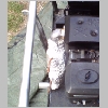
Left side view with the new control box

http://www.packratworkshop.com/pics/ctrailer3-b9.jpg
Right side view

http://www.packratworkshop.com/pics/ctrailer3-b13.jpg
Rear view

http://www.packratworkshop.com/pics/ctrailer3-b10.jpg
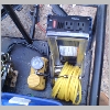
Controls closeup

http://www.packratworkshop.com/pics/ctrailer3-b12.jpg
Rear view of extra muffler

http://www.packratworkshop.com/pics/ctrailer3-b14.jpg
Close up of extra muffler with built in heat exchanger
http://www.packratworkshop.com/pics/ctrailer3-b15.jpg
Top view of extra muffler
http://www.packratworkshop.com/pics/ctrailer3-b17.jpg
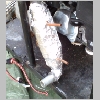
Air compressor and 12/110 inverter
http://www.packratworkshop.com/pics/ctrailer3-b16.jpg
Completed Trailer with side covers and cargo lid installed
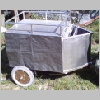
http://www.packratworkshop.com/pics/ctrailer3-b18.jpg
This was the orginal configuration of my first power assist trailer that could be pulled behind my trike or mobility scooter and allow either one to run as a hybrid type system.
———————————————————————————————————————————————
It has since been modified and the 6.5hp switch for a 2.5hp and the 24v alt removed and a marine battery put in it’s place. It still has the 12 vdc to 110vac inverter and the small air compressor but no longer puts out 24 or 36vdc. The original text is below.
———————————————————————————————————————————————
It supplies power from a Harbor Freight 6.5 hp engine turning two different car alternators. One is an automatic type for 12v systems and the other is an automatic type setup for 24 volt systems
The outputs are as follows:
12 vdc at a maximum of 60 amps maximum for 12 volt tools, the trailer lighting system and power for the 12/110 volt inverter.
24 or 36 vdc at 50 amps maximum for the motor systems of the trike or mobility scooter.
110 vac at a maximum of 1000 watts (supplied by the 12v alternator system)
Compressed air supplied by a small 12v air compressor.
|
Here is a basic view of what the trailer should look like when I get done although the control box has been changed a bit as you can see in the picture of the control box and wiring below. |

|
The beginnings…. bed rails and electrical conduit. |
bits are brazed together |


Wheel plans. These wheels are no flat types I recycled from some wheelchair wheels. I could not use the original hubs so made some new ones from stainless steel sheet metal and hubs will ball brearings already mounted cut from those cheap $5 10″ wheels Harbor Freight has on sale all the time. The centers of the wheels are made from laminated plywood.
|
Layout plans for the wheels |
Here is a pic of the original pieces of sheet metal and the hubs. |


|
Circles cut out and ready for assembly. |
All the bits assembled |

I decided I would need some kind of brakes on the trailer. The simplest thing I could come up with was a inertia driven cable system. The tongue slides in and out of the trailer frame and causes a cable to tighten up and activate the band brakes on the wheels. The tongue is spring loaded in each direction to smooth out any jerks in movement. It works quite well.
|
Here is the layout of the braking system |
I had to make the brakes, bands, drums, everything to be able to get what I wanted. Here is the layout. |


|
This is one of the brake drums showing the slotted edges with the screw holes and one wood ring glued and clamped down while it sets. There is another ring that got glued over it. |
This is a shot of both drums after they have been assembled. All the screws have been put in and the outer faces have been turned down flat on my lathe. In the picture you can see the resin mix that covers all the screw heads. Once set this will be sanded smooth. There is tape around the leather band in the picture to both clamp it tight while it sets and to protect it from drips from the resin on top. |


|
Painted and ready to be installed |
View of brake and components |

|
Close up of cable connections on trailer pull bar and pully setup |
View of entire bottom of trailer showing entire brake system |


|
Here is the bottom section showing the metal wire tabs being fiberglassed on in preperation to fiberglassing the entire surfaces |
Controller and main power wiring diagram |


|
Left side view with the new control box |
Right side view |


|
Rear view |
Controls closeup |


|
Rear view of extra muffler |
Close up of extra muffler with built in heat exchanger |


|
Top view of extra muffler |
Air compressor and 12/110 inverter |


|
Completed Trailer with side covers and cargo lid installed |
