The Pack Rat Workshop Minto Wheel Page 1 |
Page 2 |
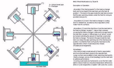
The Wallace Minto wheel is a very simple device. It works simply by using the pressure generated by a liquid that has a very low boiling point. The liquid is pumped from the lower tank to the upper one and gravity does the rest. The simplest method of heating the liquid is by submersing the lowest tank and a tank of hot water. This can be supplied by solar panel extremely easily. The basic minto wheel operates at a very slow speed. This is normally less than 5 rpm and normally only 1 or 2 rpm. What the wheel can supply is alot of torque at that slow speed and so it can be geared up to a higher speed. The basic wheel as generaly built has some limitiations though due simply to the way it is constructed. Most designs tend to heat the entire lower tank of fluid and then try to pump it through a fairly small pipe to the opposite tank. In the pics along the bottom of the page you can see one of the original wheels and a “Mother Earth’s News” version they built to try out the idea. (click any of the pics for larger views) |
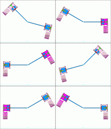
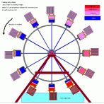
This is one of my first ideas to do away with the limitations I mentioned above. First instead of heating all the liquid each time this method will only heat a small amount of the liquid between the bellows and the outside of the container. This contaner will provide a large heat transfer surface to the operating liquid. This will allow me to use a much smaller amount of the liquid. Just enough to create the needed pressure and no more as what will actually be transfering back and forth will only be water. This pressure will act on the water filled bellows inside of the container to transfer the water to the opposite bellows through a pipe at least 1 inch in diameter. This should allow the operating liquid (propane, dichloromethane, freon R-12 or R-11, etc……) to condense into liquid and flash boil at a faster rate allowing a faster rotation. The right pic is a Minto type teeter-totter incorporating some of my suggested improvements. I didn’t draw the tanks into the picture but the ends would dip into the hot tanks at the bottom of the cycle just as a wheel. |
This is a modification by Stuart Brown. It solves one of the main problems with heating all the operating fluid by using a flat plate under each container to transfer the heat into and out of the fluid at a faster rate. |
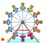
The left picture is a full size wheel using water as the weight that is shifted and propane or butane as the low vaporising fluid. There is a free floating piston that seperates the water and the operating fluid/gas. This setup allows for the use of only a small amount of fluid/gas for each cooling/heating coil. The actuall pressure can be set for the operating temperatures used. The second picture is also a full sized wheel. It worked just like the one above but uses a flexible rubber diaphram instead of a piston. Since the system really only needs about 15 psi to operate the shells for the diaphrams could actually be made of reinforced plastic. This would keep the fabrication cost per wheel down. The next three are my attempts at designing one of these that would be cheap to build. They use small throwaway propane cannisters as the boiler tanks and wheel inner tubes inside pvc pipes to pump the water. The gas heats up, fills the tubes and the water is forced out the pipe to the opposite pipe. |
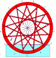
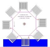
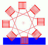
Adam Hayek , one of the other members of the Yahoo Minto group had an interesting idea about using check valves and a different piping setup for a wheel design. His version uses 13 tanks and hooks them up every 5 tanks with a check valve to force the fluid in the counter clockwise direction. His design is a bit more complicated but it should be more efficient that the regular setup. If clear tubing could be used this one would be very interesting to watch while operating. |
I used his idea and drew up my own version of it. This one is a bit simpler but I think it would work much better than the original also. Overall it works like the normal minto type wheel. I have it broken up into 2 different fluid circuits in this pic. The check valves force the fluid in one direction causing the wheel to turn in a counter clockwise direction. The third pic is a combination of Adam’s piping scheme and my idea of coil type heat exchangers instead of tanks. This is one single loop like Adam’s design above but only using 8 heat exchangers for drawing simplicity. |
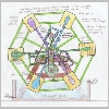
This is a small wheel for a Minto design as it is only about 6′ in diameter but it works also quite differently from the regular wheel. In this design the power from the wheel actually comes from 3 hydraulic motors that are tied with a bike chain to a center gear. Each motor has a bike freewheel mounted on it’s output shaft so the chain can run free when it’s not being powered. The hydraulic motors are powered by the fluid being pumped from the bottom tanks to the top ones instead of having just a straight pipe between the tanks. The wheel still spins but the motors spin with it. The wheel drive shaft that all the frame is attached to has a small sleeve on the front between the wheel and the front wooden A-frame. Only the rear of the frame is shown in the picture. It has ball bearings between the main shaft and itself. On the outside of the sleeve is mounted two gears. One is fed by the motors and the other one feeds the lower output gear that a wind turbine types alternator is mounted to. That alternator doesn’t have to be on the bottom, that’s just the only clear place I had on the drawing to put it. This allows the output of the hydraulic motors to be seperated from the output of the wheel itself. The tanks on the wheel are actually diaphragm type tanks that go on a potable water pump system that have a 1.2 gallon capacity. With the 2.32 cu” motors this will give about a 520 rpm output on the alternator if the tanks are raised to a 100 psi differential between the top and the bottom tanks.
This equates out to about .25 hp or after driving the alternator about 15 amps at 12 volts to a battery charging system. If a spiral tube pump setup was installed on the backside of the wheel, the system would also be able to pump it’s own water to and from a solar hot water panel because the wheel has a turning torque of about 25 lbs. |
Page 2 |