Pack Rat Work Shop 
   Air motors/Steam engine idea/designs

WorkShop Index       Alt. Energy Index  

Page 2–>  Page 3–>

                                        Air motors General Suggestions and possibilities

 Before I get into drawing all type of air motor designs I thought that pointing out some items that could already work well and can be bought off the shelf might make things a  little simpler for people without machine shop capabilities.

Possible choices:
1: air powered drill  or hand grinder
2: small air motor from a surplus dealer
3: small air motor from new supplier 
4: steam engine  

 The next simplest possibilities would be converting a small gas engine to run on air by modifying the valve setup or using a 2 cycle style.  This would probably work simplest by  using a small 1-3 hp type where a new head could be created allowing the engine to use a bump valve to control the air.  This setup would also require an electric starter motor to initially turn the motor over before it would open the air valve as a bump valve motor is not self-starting.

From there we build a motor from scratch.  This type will require some machine shop capabilities. 

BUZZ Generator Systems 
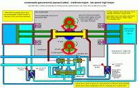
Combined compressed gas motor/generators


 These are two options that combine an opposed piston compressed gas engine with an alternator system in one package.
 Two versions shown – large and small  

 (There are too many pictures for this page so they have their own page)

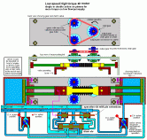
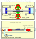
Slow speed reciprocating air motor
 with high torque rotary output

This is a very simple air motor that will operate with a small air supply as it will keep going in each direction untill the pistons reach the full travel on each end. Each piston has pressure on one side when moving and doubles the output power. 

  The design is based on an air powered diaphram type water pump was used back when I was in the Navy when we where in the shipyard. I searched the net and finally found a simple diagram of the valve system that the pump used. I think the company probably has it patented so if you want one, you’ll have to go to them and talk them into building this system. 

It is actually a very simple double acting pump setup but the way that the valves operate forces the the pistons to move with full travel on each stroke. This redesigned motor system uses opposed double acting pictons instead of diaphrams like the original pump.  This allows a half gear to operate with two gear racks to give the output shaft a single continous direction of rotation as long as the pistons are moving.  The slow speed description does not mean only a few rpm a minute. This setup should be  easily capable of operating at a couple hundred rpm output depending on the size of the pistons, valves, tubing and the amount of compressed air available.   It is such a simple setup where the valve system does all the work that  it can be scaled up or down as needed for speed or power very easily simply by changing the size of the pistons and gear/rack.

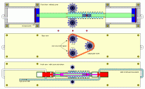
The second version uses the same idea but uses one-way clutches and gears with a chain to feed the output gear. It also show how with 2 3-way valves the system can be used with a single or both pistons pushing on each cycle…. a kind of low or high power setup depending on the valve positions.

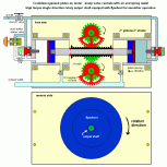
The third pic shows a mangle rack type of setup. The red gear segments are driven by the rack on alternate directions of the pistons. The green gears are mounted directly to the red segments and turn the blue center gear in only one direction and continiously as long as the motor is operating.

Simpler version of air motor above

 This is just a simpler version of the previous air motor. The valve system has been  simplified while working in almost the same way. This uses a 2 cycle exhaust type system where the air is exhausted directly from the bottom of the cylinders from holes drilled through the cylinder walls just above the valve rings at the end of piston travel. The air inlet for each piston uses a very simple slide valve that is moved only the last inch of so of each piston stroke. These are operated by the little orange pin and purple slide arrangement shown in the picture.

Even smaller version air motor

 This is  an even simpler version which uses spring loaded valves configured as a bump valve motor but instead of the piston having the pin it is mounted on the valve itself. The valve is a simple slide valve with a spring return spring.  The motor has to be started by using a small extra valve connected between one cylinder and the air supply temporarily to move the pistons to one side and operate the other supply valve.  As soon as the first exhaust is heard the starter valve is released and shuts.  The motor should continue to operate from this point. This motor would work best driving a flywheel with power removed from the flywheel with a different belt or chain setup.  The pic displayed shows a motor with 2″ diameter pistons with a 2″ stroke length. It would be less than 12″ in length and 6″ high and 3″  wide.

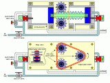
Mangle rack gear setup  air motor

 Here I have changed from using clutched gears and a chain to simple mangle gears. This allows the center gear with output shaft to turn in only one direction. If used with heavily built gears and 4-6″ pistons a very large amount of torque for the motor size would be created. The picture on the left shows the system with 2″ pistons with 2″ travel.

The second pic is a bump valve version of the one above. The back shows the flywheel that should be used for the smoothest operation

        Some Example drawings of possible steam/air engines 

  These are some more examples of simple steam/air types of engines that can be built for use with minipower system.  They are all 2 cylinder or above but the basic designs will work with one cylinder. They can be scaled up or down as needed so I didn’t add  dimensions to the drawings.
  They were drawn on 1/4 inch graph paper though so that will give some idea of comparison measurments to draw out a real set of plans.  All these engines would require an oil lubricator added to the air inlet line to provide lubrication to the pistons and cylinders.  This is not needed when using steam. 
  You will notice that all these drawings have one thing in common. I tend to use a simple exhaust system when designing steam engines. The exhaust goes out through the cylinder walls at ports like a two cycle gas engine. The cylinders are surrounded by another shell that would have insulation on the outside. The reason for this is that it helps keep the cylinders hot.   This will not work using them as an air motor as it would eventually build up ice between the cylinders and the shroud.  The cylinders would have to has individual exhaust ports mounted with no shrould around them.
 

AMSM30.JPG

2 cylinder single acting

spin valve inlet
2 cycle style exhaust
internal and
external views

AI2C9C1C.JPG


2 cylinder single acting

Spin valve inlet
Alternative version of engine on left

AMSM20.JPG


2 cylinder single acting

Standard slide valve
type inlet

2 cycle type exhaust
conventional setup

AMSM21.JPG


2 cylinder single acting

Rotary valve inlet
2 cycle style exhaust


AMSM33.JPG

4 cylinder single acting

internal view

spin valve inlet
2 cycle style exhaust

AMSM33A.JPG


4 cyl double acting

external view

Page 2–>  Page 3–>