|
Pack Rat Work Shop |
|
All the drawings/plans here are the end result of me trying to figure out how I can add some wind power alternative energy resources to my home and workshop while living in a subdivision. I have two major drawbacks implementing any wind power idea in my area though. #1 Our average wind speed around here is Wilmington , North Carolina is only about 10-15 mph although because we are on the coast we do normally get the daily “to and from” winds from the ocean. #2 I can’t put up any kind of tower more than a few feet above my house’s roof level because the lot is far too small, too many electrical wires and local zoning. |
| Wind and solar
|
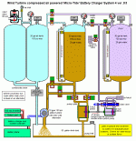
Micro-Tide system 4 ver. 03 This is the third version of the ‘Micro-Tide’ system 4 . This is a low power system that would generate about 400 watts max at 12 volts dc. Unlike that last systems this uses compressed air supplied by one or more wind turbine driven air compressors. It uses solenoid control valve on the hydraulic motor also that will allow the system to build up to maximum pressure before it starts each run cycle. |
||
| Wind and solar
|
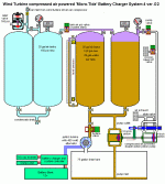
Micro-Tide system 4 ver. 02 This is the second version of the ‘Micro-Tide’ system 4 . This is a low power system that would generate about 400 watts max at 12 volts dc. Unlike that last systems this uses compressed air supplied by one or more wind turbine driven air compressors. It uses solenoid control valve on the hydraulic motor also that will allow the system to build up to maximum pressure before it starts each run cycle. |
||
| Wind and solar
|
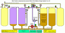
Micro-Tide system 4 ver. 01 This is the first version of the ‘Micro-Tide’ system 4 . This is a low power system that would generate about 400 watts max at 12 volts dc. Unlike that last systems this uses compressed air supplied by one or more wind turbine driven air compressors. It uses solenoid control valve on the hydraulic motor also that will allow the system to build up to maximum pressure before it starts each run cycle. |
||
|
|
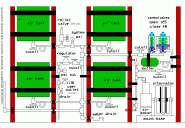
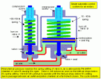
Different Mini Power Plant (basic setup) This is an alternative version of the system above. The difference is this setup is purely mechanical. The air motor is turned on an off with control valves operated by the inlet air pressure. It is designed to turn on at approximately 125 psi and turn off approximately 40 psi. The second pic is an enlarged view of the control valves so the operation can be plainly seen. |
|
Water pump operated by small air compressor This is a simple little pump with only 3 moving parts. A piston, piston return spring and exhaust piston/valve. The theory of operation is very simple. A small air compressor such as you get a any ‘large-mart’ that runs on 12 volts from your battery is dissassembled and the little electric motor exchanged for windmill blades. It is then mounted on a frame and put on the top of a pole!. The small air compressors are generally rated as much as 250 psi but that will not be needed here. The pump is actually capable of working with the full output pressure of the compressor and pump water pretty high up if needed though – the pump would have to be built out of all metal for reliability though I think in that case… I plan to use pvc pipe and only about 10 psi output presure maximum. 1) The air from the compressor is fed on top of the piston forcing it down and pumping the water out. 2) The exhaust delay valve is prevents the pressure from acting on top of the exhaust piston/valve 3) The pressure on the exhaust piston builds up and forces the exhaust valve open and vents off the 4) The piston return spring to raises the piston back up refilling the pump casing with water. As the The exhaust delay valve should also be adjusted to to allow the faster operating speed possible for the amount of compressed air supplied. Orifices could be used instead of valves and a table built up to match various air supply capabilities but valves are simpler and quicker to set. |
|
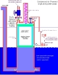
A WIND POWERED HIGH AND LOW PRESSURE AIR COMPRESSOR THEORY OF OPERATION: The water from windmill driven pressure washer pump will be used to displace air from an upturned nitrogen bottle. When the bottle reaches a certain weight (bottle almost full -almost all air forced out), the air powered controller will stop the water input to the bottle and allow the input to go to atmospheric psi allowing the water to drain back into the tank (pump will be bypassing at this time directy back to tank). When weight drops to certain point on the bottle the controller will again allow water back into the bottle. This will continue untill the bank of hp tanks reaches approx. 1500 psi and then the controller will simply use the 125 psi air and an air powered disk brake to stop the rotor and pump. At 1200 psi the controller will release the rotor and the process will start all over. Air from the HP tanks will go through a reducer to 125 psi and fill main use tank. The HP air could also be used for filling paint ball marker tanks if you are into that. LP Air can then be used for whatever needed. This is not a high capacity flow system but since it would be fully automatic and can fill when ever there is wind day or night it would be cheap source of air to use . I had thought about using a small hydraulic pump as it would be able to do other stuff too but I don’t think I want the fluid at 1200- 1500 psi in contact with air (the system will be slow enough that heat generation wouldn’t be a problem but I don’t see any point in taking the risk of a possible fire or explosion due to some sort of compression effect. |
Alternator and Generator Information
|
Alternators / Generators There are many different routes that can be taken here. A simple car alternator will work just fine if the gear ratio to the air motor is set up correctly. A car alternator would require a larger motor though. And then for the builders of the group a hand built alternator of the windmill type that uses a car wheel brake disk setup or something mechanically close to them with large magnets and hand wound coils. This setup gives the most capability to match the air motor or windmill blades as this style can be scaled up or down as needed. These sites below give almost all the info you might need on how to build an alternator or generator by hand. They are designed primarily to be operated by windmill blades but can be driven by any motive force. You can also learn how to make the windmill blades on these sites. It’s alot easier that you might think! Voltage and current outputs of these handmade alternator are generaly as higher than any premade for the same price (if you can even find one priced that low – The cost of building one of the disk brake designs is less than $300 unless you are designing something really big. Normally the magnets are the biggest cost but the price of copper has gone way up lately so they are getting a little more costly to build. That is still far below the normal retail of a commercially made equivalent output model though. You don’t need a machine shop to build them either which is another nice plus. They also show some of the various small motors that are commonly used as generator / alternators. |
