|
Two new full sets of plans are now in the library. A delta recumbent trike and a tadpole recumbent trike |
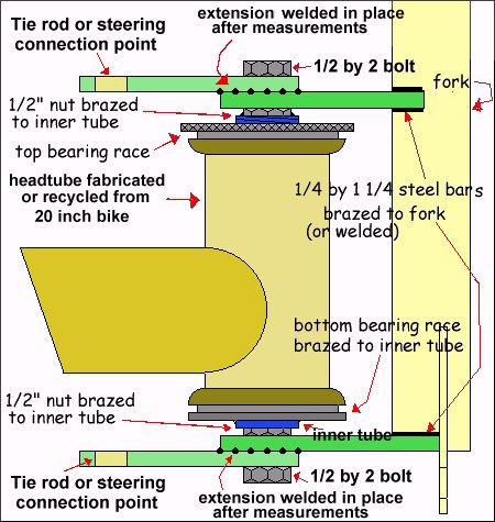
Headtube Adaptation for steering using forks instead of stub axle
|
|
|

|
This is the latest type of headtube/steering setup I have been using. This is duplicated on each side. The bar at the top connects to the tie-rod end bearings and is welded onto the bar section coming from the fork after measuring for the Ackerman compensation required. The center tube of the headtube has a 1/2 inch nut brazed into each end. The lower bearing face is brazed directly onto the inner tube about 1/4 inch up from the bottom of the tube. This inner tube is simply bolted between the two bars that are welded to the fork on each side. this is not the lightest system around but it is strong and takes abuse well. There is no wheel camber shown in the front view drawing but I normally try to use about 12 degrees. |
Differential for trikes or 4-wheelers

|
This is a simple differential to make if you are trying to drive both rear wheels. It will drive both wheels when going straight and the inside wheel when turning corners. I have used it on a 4 wheel bike and it worked without any problems. The biggest problem when making the thing is being accurate when drilling the holes through the center gear. I made a wooden template of the free wheels and then turned each side down on a lathe untill one side would just slide into the hole in the center gear and the other side would just fit into the plywood shell ends and that enabled me to get the bolt holes lined up pretty well. Mine was made using every other tooth space on the 14 tooth free wheels for the 1/4 inch threaded rod.(probably overkill but I wanted to ensure it would be stay together and not twist the rods out of alignment with a heavy load.) I used 5/8 inch plywood painted with fiberglass resin with two layers of cloth and I sealed washers under the cloth at all the holes for the freewheel spacer rings which worked ok but it would probably have been better to use aluminum or plastic rings. The parts were stripped from the 4 wheeler after about a year for other projects but the differential was still in good shape and working fine. |
Cheap Rod end Bearings

|
This is a very cheap and simple rod end bearing that I was originally using for the steering on my various trikes. After welding use a tap to chase the threads in the nuts and the rod couplers to ensure the threaded rod ends will still turn normally and free. Make sure the hex bolt holding the 2 eyebolts is torqued fairly tight into the inside eyebolt and use some locktite if you can want to make extra sure it will stay put. Helpfull tips: Another alternative is wrapping the eyebolt threads with teflon plumbing tape before assembly. This works OK for a while but loosens back up much faster than the sealant method. If you need to dissasemble the bearing often for some reason though it is a lot faster and less messy during reassembly |

|
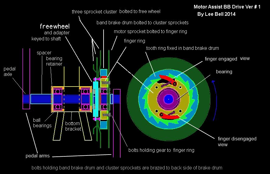
Over on one of the Yahoo assisted bike forum boards we were having a debate about the pros and cons of a bb drive. It got started over the new Bosch bike with the fancy bb drive that contains the motor, electronics and battery all in one case. I don’t personally care for puttng the electronics and battery in the same box as the motor as that will subject both to heat that they don’t need. I feel that the Bosch version is WAY overpriced and you can do the same thing much cheaper. For less than $500 easily. So I sat down and drew out a simple diagram of a much cheaper way to make one. I didn’t show the motor in the picture. Pretty simple to actually to do it if you have access to a lathe and mill like I do.. But it can be done with simple hand tools and a drill but it would just take longer to make the parts. Use a regular 5/8″ keyed shaft between the pedals and modify and bolt the sprocket cluster to a freewheel mounted backwards on the shaft with an adapter so the shaft turns the freewheel when pedaling and not the other way around. Bolt one of the 108mm scooter type band brake drums onto the outside of the cluster where it’s bolted to the freewheel. A simple ball bearing is mounted outside the freewheel on the shaft with a milled ring around it to hold the motor drive sprocket and a couple of fingers/arms like a freewheel uses. Have someone use a 3d printer to print out a plastic (nylon) tooth ring that fits inside the band drum ( it will be glued or pinned into the inside of the drum) that will work with the arms on the milled ring. Then when you pedal it doesn’t turn anything but the cluster sprocket since the arms of the finger or arm ring is kept pulled in out of the way when the motor isn’t running. When the motor is turning it also turns only the cluster sprockets and the pedals stay still unless you want to pedal along with it. A couple of spacer tubes on the each side between the pedal arms and bb parts will keep everything in position. The fingers/arms are actually spring loaded to keep pulled in until centrifugal force throws them out to catch the tooth ring when the motor is running That way there is no clicking when just pedaling. Kind of works the same way as a starter cord on a lawn mower. It wouldn’t add but about 1/2″ thickness to the pedal arm axle. The motor could be mounted in front along the angled triangle frame tube or on the upright for the seat tube. |
MISC 3 and 4 WHEEL DESIGNS
|
|


|
These are original designs for my last trike addition to my backyard parking lot. |
|
|
|


|
I’ve been considering building another bike truck. This time though it will be a two person setup so my wife can ride with me. -update- I found out 4 wheel bikes are not legal on the roads here in N.C. – As shown in the left drawing, a 1 hp 48vdc motor will be also mounted withen the frame. The electric assist helps a lot with my bad leg and a 50 amp hour battery should give it about 2.5 hours of power by itself. The pic still has some work to go as I need to add the brakes , cable layouts and electrical layouts but enough is there to give a good idea of what it would look like when finished. |
|
|
|


|
These were my original plans are power assist charger trailors that I wanted to build (either one) to provide longe range for my e-assist recumbent trike. I decided it would be easier to just turn two 12v car alternators to keep the batteries charged instead of trying to find a 24v version I can actually afford. From what I have seen on the net, you can buy 3-4 regular 12v alternators for the price of one 24v type. I have since built three different versions but used 24v alternators and 2 wheels on them instead of one like the in the pictures. I finally found a reasonable priced source of 24v alternators on ebay. |
 |
 |
|
This is a yard/sand/beach type trike. The ideal setup needs for it to be adjustable from kid to adult size. The steering in the drawing is setup with a chain to go from a small gear mounted on the center of the handlebar pivot to another gear at the center of the front wheels. The chain will have a number of removable links and a rope tensioner so it can be adjusted as needed when the seat is moved. I may just use push-rods instead, I haven’t totally decided yet. The axle that the front gear is mounted on goes through a tube welded vertically through a hole in the main beam and connects to a linkage bar underneath that controls the steering connecting rods to the front wheels. Changing the steering gear ratio from 1/1 will alter the steering from very easy to twitch and crash. The front wheels will be mounted with standard go-cart kingpin setups as they are cheap and easy to come by locally. They are actually cheaper to buy than the materials it would take to make them. It will be built from the same 1 7/8″ diameter muffler pipe that I am building the full size trikes from. I know it will be a little heavier than it needs to be for a child but I want the frame to be very strong and be able to take a lot of stress even from an adult and that size pipe has taken all the abuse the I can give on the trikes that have been built so far. It uses an middle gear setup to get a higher gear inch range so you don’t to pedal yourself silly to get a decent speed. I don’t intend to try to install a multiple gear cluster on that small rear wheel. A cluster could be easily be installed instead of the single free wheel on the middle setup though as the free wheel can be reversed with the driving gear so it is on the outside and a stud could be mounted right below for a derailler instead of be mounted further up the frame as the picture shows where it normally just takes up the slack from the front gears. I should be able to give it 1, 2 or 3 speeds based on the gear cluster at the pedals. This setup also will allow me to hook up a gas engine or electric motor on the middle gear setup through a freewheel on the other end of the shaft without having the motor or engine turn the pedals. |
|
Two new full sets of plans are now in the library. A delta recumbent trike and a tadpole recumbent trike |
Misc plans
|
The following drawings are all scans of various designs created over the last few years. As you can tell from some of the data in them I have considered selling and renting a few of the versions locally. |

|

|
 |

|

|

|

|

|

|

|

|

|

|
|

|

|

|

|

|

|
|

|

|

|

|

|

|