|
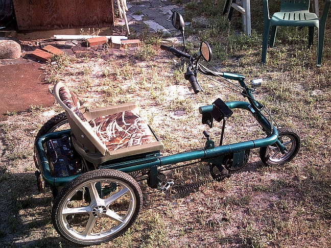
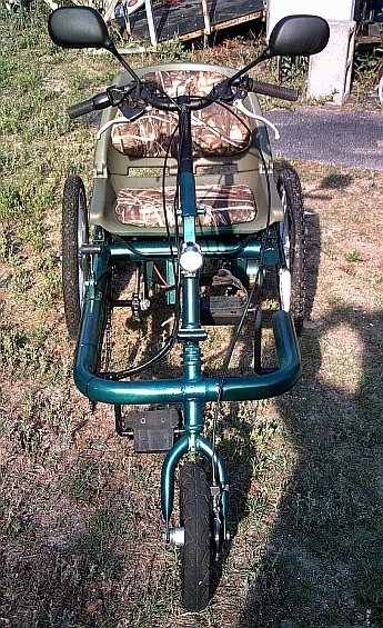
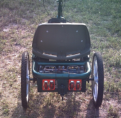
Originally setup with pedal side right rear 6 speed rear derailleur…mid range easy to pedal gearing. This has been changed over to a single speed. My wife (the trike’s rider) didn’t like the multiple speed setup and prefered just one. It’s now using only the 4th sprocket of the 6. (2) 33amp 12v sealed lead acid scooter type batteries. Frame made from 2″ auto exhaust tubing .066 wall thickness Weight 115 pounds total with 55 pounds of that battery weight. Front and right side rear modified scooter band type brakes activated from steering tiller/handle bars Left side rear modified scooter band type parking brake with operating handle mounted on left side of frame beside seat. Lighting 10w 24v front scooter light 4 led type tail lights. (12v semi truck side marker lights with two wired in series for 24v on each side of trailer hitch.) Dual mirrors mounted on steering tiller Pin type trailer hitch on rear for bike trailer. I have 4 different trailers. Three cargo types and one with an engine and 24v alternator that can be hooked up to operate in hybrid mode for extra long range. Handle bars adjust up or down as needed at mid pivot point. Can be released at the base and flipped forward as a handle to pull trike like a wagon 12″ front aluminum wheel with no flat foam tube inserts within the tires 5/8″ dual rear axles Total costs with new batteries…. approximately $1100
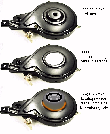
My original drawing plans. It ended up pretty close to them. I didn’t like the way I had done the rear brakes as the shells were scrubbing on the rear axles and making a bit of noise. I took the rear axles off and added some bearings to the shells. This way it keeps them centered and also reduced the friction on the axles a bit too as well as stopped the noise. They turn easily and very quietly now. Here is a picture/drawing of what I did to the brakes shells. The bearings are 1 3/8″ outside diameter with a 5/8″ center hole.
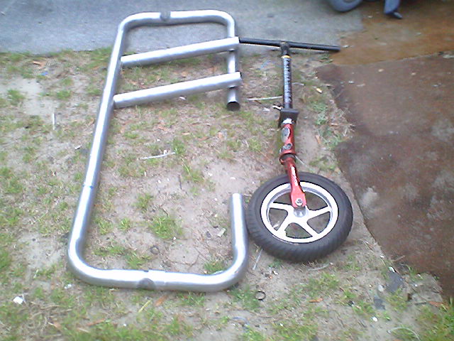
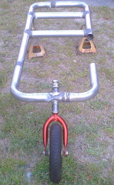
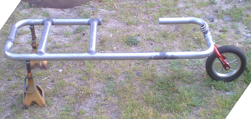
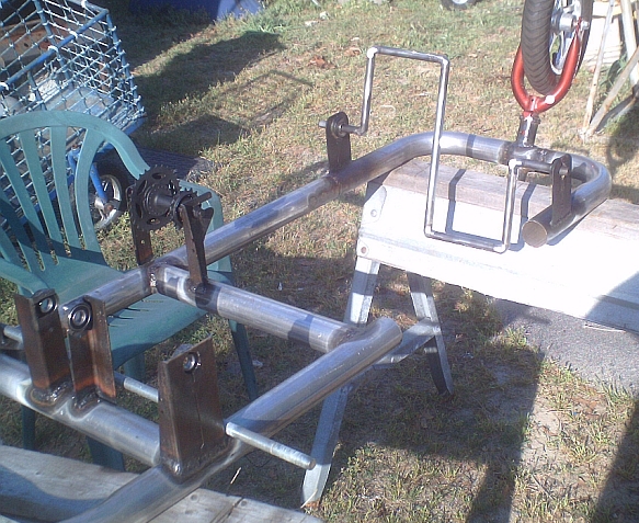
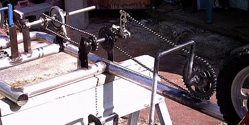
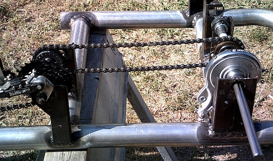
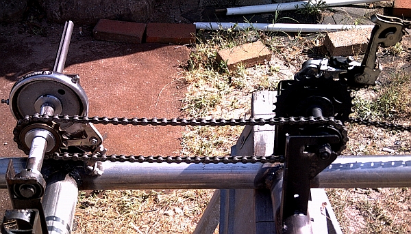
Below are some pictures taken while the trike was being built.
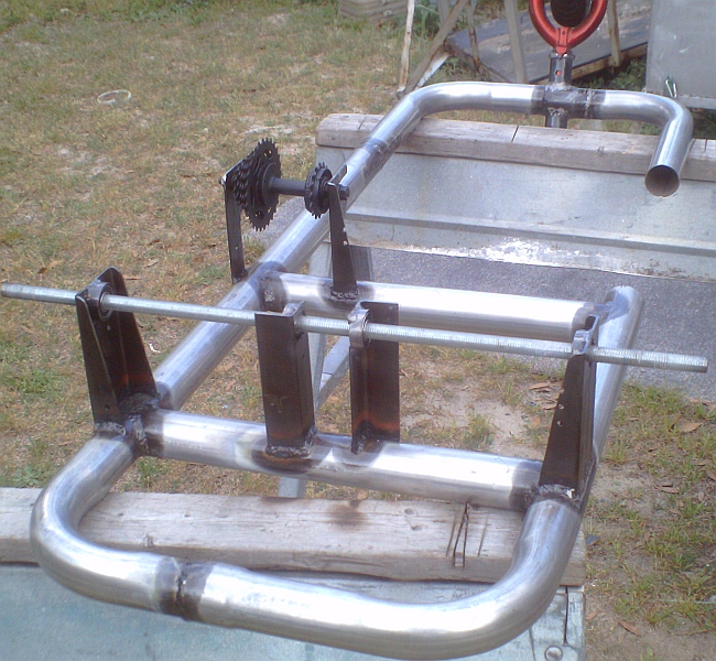
This jack shaft has been the most complicated thing I have had to make for the trike. It consist of a a 13t regular 3/32″ thread-on bike sprocket and a thread-on 90t #25 chain sprocket. A 12″ aluminum mag wheel hub I cut the rim off that already had free wheel threads on both sides of the hub and that made my life a bit easier. I stuck the hub on the lathe and turned down both sides so I could add an extra 1/2″ of threads on each side. Then I bored out one side so the bearings would fit in to a short section. It was removed from the lathe and stuck in a vice so I could add the extra threads manually. I have a 1 /3/8″ x24 die and big handle that was bought just for these projects. Then the 90t and the 13t sprockets where screwed onto the unbored end and cut if off behind the 90t sprocket. The two sprockets were then brazed together where they butted up against each other on the free wheel threads. I managed to get them brazed in a few spots before the aluminum free wheel thread melted out of the center of the sprockets. I used that side of the hub as a sacrifice part to be able to get the sprockets aligned properly and then brazed together. If I had an electric welder I probably wouldn’t have had to do it that way but using a torch there wasn’t any other way I could think of to do it. The sprocket’s threads were then cleaned up and rescrewed onto the other half of the hub. They went on there very tightly too as I had to use a 2′ breaker bar to screw them all the way on. The sprockets and free wheel hub were then cut off what was left of the original wheel hub. I’m not in the least bit worried about the sprockets screwing off the hub while in use. There is really no way to get them off other than by melting out the center again. They are screwed on TIGHT! After cleaning up the center boring a little bit the bearings were then pressed back into what was left of the free wheel hub so it will ride on the original scooter motor mount frame bolt again. It was a bit of effort to go through but I ended up with a nice tight package for the jack shaft that will work with the original mount. The alternative was to make a totally different motor mount and use a shaft with bearings and the sprockets mounted on the end. The way I did it was about $25 cheaper. Below is a picture showing the jackshaft. The rear wheels use keyed drive hubs I used 5/8″ to 1 3/8″ free wheel adapters that I turned down slightly on the lathe to fit into the side of the hubs. A 1/16″ thick piece of sheet metal was then brazed to each insert. The edges were cut so I could bend them down and then add screws to hold them onto the plastic hubs. There are 15 screws holding each insert on so they should stay there. The opposite side spacers were made from some large brass sleeve bearings I saved from something I took apart. I had to turn them down slightly to fit the hubs also. Below is a picture showing both wheels before cleaning them up and painting them. |


