Would It Work?
Would these actually work? Are ‘perpetual motion’ machines actually possible? Well, I don’t know the answer to that question any more than anyone else , standard physics says no but it’s fun to design, build them and find out. Who knows? Sooner or later someone might actually stumble across some design that does work or works with a very small input to create such a large output that it will be close enough!
Just click on the pics to see the large versions.
Magnetic Assist Minto type Gravity Wheel
I decided to try to come up with a different version of a Minto type gravity wheel. I’ve already done a number of different designs and so I decided this one would have to be really different.
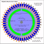
The 48 2″ long tubes around the outside circumference contain 1″ long 1/4″ diameter cylindrical super magnets ( approx 1 oz weight apiece ) and can slide back and forth for 1″ distances. The magnets all have their north ends pointed into the center of the circle. The green magnets cause the tube magnets to slide back and forth in their tubes depending on where they are around the circuference of the blue wheel.
On the right side the tube magnets are pushed out to the ends of the tubes and on the left side they are pulled to the inner end of the tubes by the green stationary magnets. This should solve the problem of the weight shift needed. In this design there is approx 11 ounces more on the right side of the blue wheels axle than on the left side. This should cause the wheel to turn clockwise and it should continue to turn as the green magnets are shifting the tube magnets back and forth using magnetic fields instead of gravity.
SMOT Magnet Motor
This is another version of a magnet motor using the SMOT type setup. Here the balls are simply hooked to the end of shafts connected to a center axle (a disk with the balls embedded would work as well probably) With 4 smot’s and 6 balls there is always at least 4 of them pulling to break the magnetic lock of the other 2 when they reach the end of the smots. Since we don’t have gravity pulling the ball out of the magnetic lock at the end , we have to have more pull than lockup forces. I’m currently looking for more large ball bearings to try this setup. I might just try simple metal shapes since they don’t have to be able to roll in this design.
Update: I have built a version of this and tried every combination of magnets and positioning that I can think of and so far there I have found no way to get the thing past the sticky spot at the end of the magnets with this design.
SMOT Magnet Assist Gravity Wheel
Lately I have been playing with some various versions of magnet only motors. Yes, I know perpetual motion mchines are supposed to be impossible according to modern science but there is already a couple of small machines out there shown on the net that if are not true pm machines they still do a pretty good job of imitating one.
This is called an SMOT, I’m not sure who designed the first one but it is basically nothing more than two rows of magnets facing each other that are wider apart at one end than the other. If you put a steel ball bearing between the two rows on a non magnetic rail (to keep it centered) it will roll from the wide end to the narrow end due to the increasing field strength between the magnets. You can actually cause the ball to roll uphill easily. The picture below is an Idea by a gentleman named Greg Watson and an original animation pic was done by a gentleman named JL Naudin. I redrew it all and re-animated it so a clearer picture of what was going on could be seen. The blue bars are the magnets that the steel ball travels between. By using 1″ ball bearings the ball drops at the end of the ramp starting the sequence over again. All the plans and pics I can find on the net show the magnets as rectangular ceramic types but I have found that super magnets will work also.
This pic shows the magnet setup that is pulling the ball up the ramp.
click on the pic for a larger version that also shows the magnetic field lines. The pic was created with a program called “Visimag 3.1”
Update: I finally did get this one to keep going for a few hours after messing with it for days on end but all I could do is get it to keep turning. I could not get it to turn anything else but itself. It would probably make a great desk toy but it would be very noisy! It’s not worth the time or money to build.
Double Acting Magnet motor
This works like a simple double acting steam piston engine. Instead of steam and valves I’m using magnets mounted on wheels to supply the force interaction with a magnet acting as a piston.
The top and bottom wheels each serve two purposes.
1) They supply the timing and mounting for the magnets to push and pull the piston.
2) Both act as flywheels to keep the motor spinning when not actually pushing/pulling the magnet piston.
The wheels rotate around clockwise (facing the drawing) at the same speed and have two sets of magnets attached to each. One set has all south sides facing outwards and and the other has all north sides facing outwards.
Depending on the degree of rotation the magnets in each wheel cause the piston magnet to be either pushed away or attracted to it. The piston is pushed and pulled at the same time. This happens when the piston is moving both up or down allowing the engine to supply power on both strokes for about 135 degrees of stroke. At tdc and bdc there is a arc section where the magnetic fields are broken and where the wheels are supplying the energy to continue spinning to the next power stroke where the fields reconnect..
Timing pattern: Starting with piston at Top Dead Center or TDC
15 – 150 – piston is pushed and pulled from wheel magnets
150 – 195 – piston coasting – no force above or below
195 – 240 – piston is pushed and pulled from wheel magnets
240 – 15 – piston coasting – no force above or below
The power strokes do not start untill the piston is already past the TDC and BDC positions. This is to prevent the piston and wheel magnets trying to lock up and stopping the foward motion. The magnets on the wheel are slid sideways into the pistons magnetic field and have very little effect when not positioned directly above the piston as almost all of the rest of the machine is made from non-magnetic materials.
Update: Well, I can tell you that it won’t work with only the lower wheel and frame being built out of cardboard … my piston had too much clearence and kept binding on it’s guides…. I will try it again eventually I do know it will need alot bigger flywheel as the first prototype would try to spin by itself but my flywheel was way too small and didn’t have enough mass to keep it going in one direction and the wheel would attempt to back up every time the piston hung up a little on it’s guides. Another thing that will be altered is the length of the piston travel. 1.5″ is way too much for the magnets I have while testing only one wheel and the next one will only have about 3/4″ travel. I might also do away with the push magnets or double them as they don’t seem to have as much effect as the attraction magnets do.
Simple Magnet wheel with 1 driver
This is a very simple little setup that where the movement of the bearing on the cam causes the driver magnet to pivot back and forth 90 degrees showing either the north face or the south face depending on where the rotor magnets are at when passing.
The driver magnet attracts the first rotor magnet and as it gets right in front of it the cam causes the driver to turn parallel so one side is pulling and the other side pushes equally.
Hopefully this will neutralize the sticking spot problem and allow the driver to then continue to turn and push against the second magnet as the rotor turns away. This wheel will also require a flywheel or be heavy enough to act as one by itself.
Gravity Powered Wheel
DESCRIPTION:
10′ Wheel made from piping. 8 bellows mounted around the wheel.
Each bellows has a small wheel attached that rides against the green arc of the frame.
Each bellows is connected to the same 2′ pipe that runs completely around the wheel.
Each bellows holds 1 gallon open plus the small amount that is in it when it is compressed. The entire system is full and sealed with no way in or out for the water except for each bellows. As the wheel turns the bellows in the lower left corner is compressed as the wheel first rides against a lower section of the green arc. It stays compressed as it moves around the arc and so the water has to go somewhere. It is pumped into the bellows in the top left corner of the pic that has just cleared the arc at the same time. The water in all the full bellows on the left side provide the motive power to turn the wheel by the simple gravity.
With 2 full bellows on the left side providing an extra 16 lbs of weight on a 10′ wheel would give about 80 lbs of torque at the axle and 16 lbs of force to compress the bellows over a approx. 4′ area of the arc. It would take less than 5 psi to pump the water from the bottom to the top. Using a 2″ pipe should also allow the water to move quickly and it shouldn’t take long to move just a little more than 6 square inches of water each time. (click the pic for a large view)
I have no idea whether it would actually work as designed and all I can find says probably not.
I do know of a modification that would assist it to work (simply add NITI springs to operate along with the compression wheels like in my teeter-totters) but the basic principle would be the different and a hot water heat source would also be needed (sun- water solar panel). I’m going to try a small version of this anyway just to make sure it doesn’t or does (I have the parts for a small model , I just need the time to put them together) , you never really know untill it’s in hardware!.
|
Would It Work? |
|
|
|
|
Magnetic Assist Minto type Gravity Wheel The 48 2″ long tubes around the outside circumference contain 1″ long 1/4″ diameter cylindrical super magnets ( approx 1 oz weight apiece ) and can slide back and forth for 1″ distances. The magnets all have their north ends pointed into the center of the circle. The green magnets cause the tube magnets to slide back and forth in their tubes depending on where they are around the circuference of the blue wheel.
|

|
SMOT Magnet Motor
Update: I have built a version of this and tried every combination of magnets and positioning that I can think of and so far there I have found no way to get the thing past the sticky spot at the end of the magnets with this design.
|

|
SMOT Magnet Assist Gravity Wheel
This pic shows the magnet setup that is pulling the ball up the ramp.
|

|
Double Acting Magnet motor
This works like a simple double acting steam piston engine. Instead of steam and valves I’m using magnets mounted on wheels to supply the force interaction with a magnet acting as a piston. The top and bottom wheels each serve two purposes. The wheels rotate around clockwise (facing the drawing) at the same speed and have two sets of magnets attached to each. One set has all south sides facing outwards and and the other has all north sides facing outwards. Timing pattern: Starting with piston at Top Dead Center or TDC The power strokes do not start untill the piston is already past the TDC and BDC positions. This is to prevent the piston and wheel magnets trying to lock up and stopping the foward motion. The magnets on the wheel are slid sideways into the pistons magnetic field and have very little effect when not positioned directly above the piston as almost all of the rest of the machine is made from non-magnetic materials. Update: Well, I can tell you that it won’t work with only the lower wheel and frame being built out of cardboard … my piston had too much clearence and kept binding on it’s guides…. I will try it again eventually I do know it will need alot bigger flywheel as the first prototype would try to spin by itself but my flywheel was way too small and didn’t have enough mass to keep it going in one direction and the wheel would attempt to back up every time the piston hung up a little on it’s guides. Another thing that will be altered is the length of the piston travel. 1.5″ is way too much for the magnets I have while testing only one wheel and the next one will only have about 3/4″ travel. I might also do away with the push magnets or double them as they don’t seem to have as much effect as the attraction magnets do. |


|
Simple Magnet wheel with 1 driver
This is a very simple little setup that where the movement of the bearing on the cam causes the driver magnet to pivot back and forth 90 degrees showing either the north face or the south face depending on where the rotor magnets are at when passing. The driver magnet attracts the first rotor magnet and as it gets right in front of it the cam causes the driver to turn parallel so one side is pulling and the other side pushes equally. |

|
Gravity Powered Wheel
DESCRIPTION: Each bellows holds 1 gallon open plus the small amount that is in it when it is compressed. The entire system is full and sealed with no way in or out for the water except for each bellows. As the wheel turns the bellows in the lower left corner is compressed as the wheel first rides against a lower section of the green arc. It stays compressed as it moves around the arc and so the water has to go somewhere. It is pumped into the bellows in the top left corner of the pic that has just cleared the arc at the same time. The water in all the full bellows on the left side provide the motive power to turn the wheel by the simple gravity. With 2 full bellows on the left side providing an extra 16 lbs of weight on a 10′ wheel would give about 80 lbs of torque at the axle and 16 lbs of force to compress the bellows over a approx. 4′ area of the arc. It would take less than 5 psi to pump the water from the bottom to the top. Using a 2″ pipe should also allow the water to move quickly and it shouldn’t take long to move just a little more than 6 square inches of water each time. (click the pic for a large view) I have no idea whether it would actually work as designed and all I can find says probably not.I do know of a modification that would assist it to work (simply add NITI springs to operate along with the compression wheels like in my teeter-totters) but the basic principle would be the different and a hot water heat source would also be needed (sun- water solar panel). I’m going to try a small version of this anyway just to make sure it doesn’t or does (I have the parts for a small model , I just need the time to put them together) , you never really know untill it’s in hardware!. |
